
Lighting Control Coordination
Smart Switches for Hotels and Commercial Interiors
Coordinate smart switches and scene panels around the project country, circuits, gang layouts, wiring method, control protocol, connected loads, interface requirements, finishes and model-specific documents.
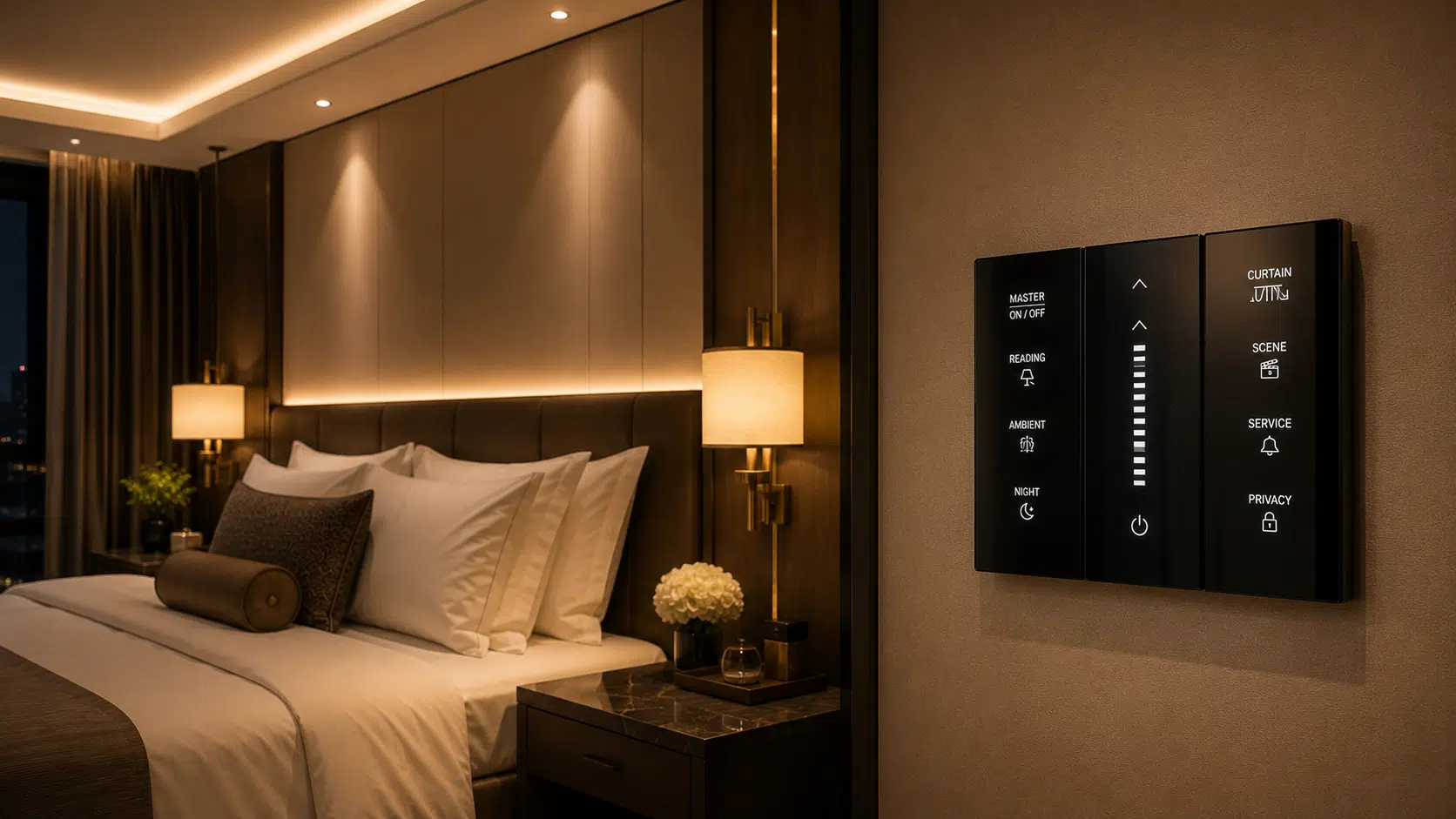
Product Options
Start With the Required Product Type
Each option follows a different selection, drawing, interface and documentation path. Confirm the relevant type before releasing detailed requirements.
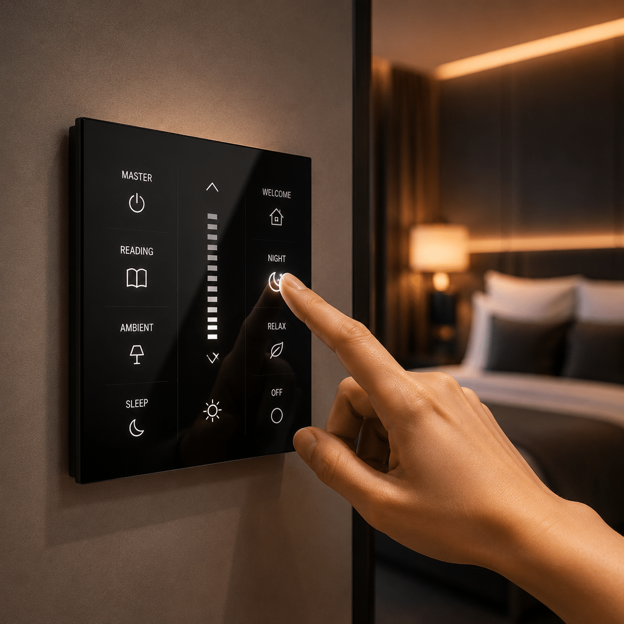
Wall Control
Touch Switch Panels
Touch interfaces reviewed for gang count, loads, back boxes, wiring and finish.
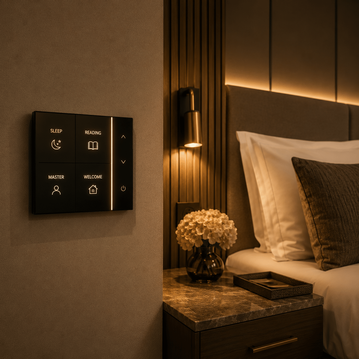
Hospitality Control
Scene Control Panels
Room scenes coordinated with the lighting-control narrative and system integrator.
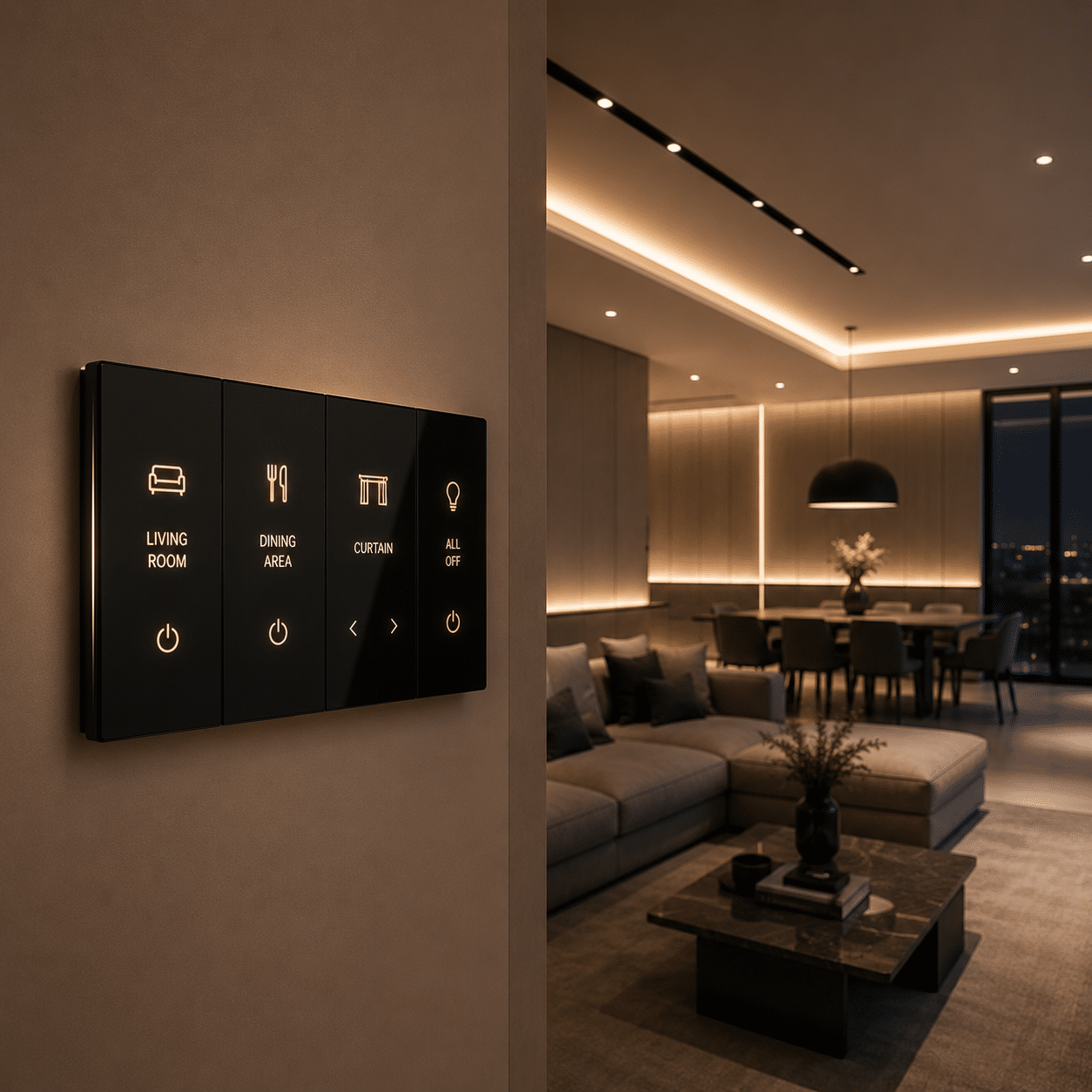
Multi-Circuit Control
Multi-Gang Switches
Multiple lighting circuits organized into clearly referenced wall-control positions.
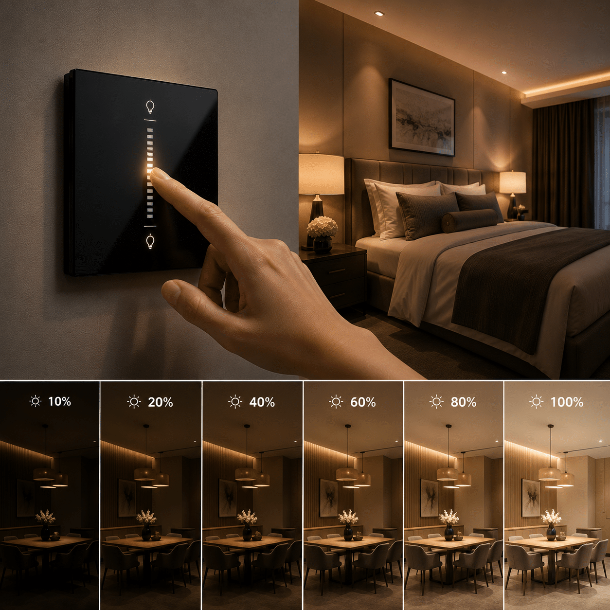
Lighting Adjustment
Smart Dimmers
Dimming devices matched to the connected load, driver and control method.
Project Inputs
Build the Switch Schedule From Circuits and Room Functions
A clear schedule connects every selection to its location, quantity, drawing reference and approval status.
Room & Position
Record room, wall location and mounting orientation.
Circuit & Load
Identify controlled circuit, connected load and switching function.
System Interface
Confirm standalone, wired or networked control requirements.
Faceplate & Label
Approve finish, gang arrangement, icons and labeling.
Technical Coordination
Coordinate the Device With the Electrical and Control System
A smart switch is not a universal drop-in component. The device, connected load, wiring, protocol and integration responsibility should be identified before approval.
- Project country and nominal electrical requirement
- Circuit schedule and connected load type
- Neutral, live and communication wiring requirements
- Control gateway, protocol and integration boundary
- Back-box dimensions and installation depth
Approval Boundaries
Confirm Compatibility Instead of Assuming Smart-Home Readiness
Protocol support, load compatibility, app access, gateway requirements and interoperability depend on the selected model and system design.
Load Compatibility
Match relay or dimming device to the connected equipment.
Control Protocol
Verify the exact wired or wireless protocol and gateway.
System Responsibility
Define programming, commissioning and integration scope.
Local Requirement
Review applicable electrical documentation for the destination project.
Finish Approval
Approve the Faceplate as Part of the Interior Finish Schedule
Coordinate color, material, icons and gang layout with adjacent sockets and the room palette.
- Faceplate material and finish
- Button, touch zone or icon arrangement
- Gang width and alignment with adjacent devices
- Back-box and wall-finish interface
- Approved room and model reference
Project Records
Keep Device and System Documentation Connected
Documents should identify the exact proposed product, configuration, revision and applicable project area.
Model Datasheet
Electrical limits, dimensions, wiring and available finishes.
System Information
Protocol, gateway and integration requirements where applicable.
Installation & Setup
Wiring, mounting, programming and commissioning information.
Coordination Workflow
From Project Scope to Coordinated Delivery
Each stage should remain connected to the approved schedule, sample, drawing and product references.
Review Scope
Organize drawings, schedules, quantities, requirements and missing information.
Compare Options
Review suitable product families, configurations, finishes and commercial scope.
Coordinate Samples
Track physical samples, model references, comments and approved alternatives.
Resolve Details
Connect dimensions, interfaces, services and supporting information.
Follow Production
Keep production and inspection records connected to approved references.
Pack & Coordinate
Identify packages and align handling, loading and delivery information.
Inspection References
Check the Agreed Scope Before Packing
Inspection points should be defined for the selected product and linked to the current schedule, sample and drawing references.
Identity & Quantity
Confirm item code, selected model or material reference and scheduled quantity.
Dimensions & Configuration
Check agreed dimensions, arrangement, accessories and interface points.
Visible Appearance
Review finish, color, pattern or visible components against approved references.
Labels & Packing
Connect package and component labels to inspection and delivery records.
Related Product
Architectural Lighting Solutions
Continue the project review with this related product category.
View product →Related Product
Power Sockets
Continue the project review with this related product category.
View product →Related Product
LED Downlights
Continue the project review with this related product category.
View product →Frequently Asked Questions
Smart Switches for Hotels and Commercial Interiors FAQ
Final products, standards, test requirements and service scope should be confirmed for the selected model, configuration and application.
What information is needed to quote smart switches?
Can smart switches be customized?
How are samples approved?
Can certifications or test reports be provided?
How are technical interfaces coordinated?
What is checked before packing?
Can several product categories be consolidated?
What should be confirmed before installation?
Start the Review
Send Your Switch Schedule and Control Requirements
Share the available drawings, schedules, quantities, reference images, technical requirements and project location. The information can be reviewed before the next quotation step.